
The amp
The Princetoad started its life in 1963 as a Fender Princeton amp. I had been debating the ethics of amp restoration and modification with a good friend, Doug Harrison, also known as The Amazing Celibate Dude. In fact it was His Celibacy who started me on my mania for old Fender amps. I already had a reverence for anything old, especially electronics, so this was a natural progression.
First I had to decide what I wanted to do. Build an amp from scratch, restore an original, or what? My first preference was to build a tube amp from scratch — that way I could say I did it all from the ground up, and if I screwed it up and destroyed a perfectly good vintage amp, Doug would never let me hear the end of it. I ran into two problems. There are numerous resources for old tube amp parts, new and used, but obtaining a replacement chassis for a vintage Fender is near impossible unless you want a tweed-style chassis — square chrome boxes are easy to make, brown and blackface chassis are not. And it was extremely cost prohibitive: assuming I wanted a tweed-style amp, which I didn't, the chassis and cabinet alone would have cost more than a vintage amp.
I wasn't about to buy a vintage amplifier and destroy it. However, if I could find an amp that someone else had butchered first, I had no qualms about finishing the job. So I set out to find a vintage amp that had been modified to the point where it no longer held any value to collectors, and strip it down to the two main components: the chassis and the cabinet.


After a couple of weeks I found it. A 1963 brownface Fender Princeton chassis, transplanted into a custom-made cabinet. The cabinet was identical to the original in every way but one — it was an inch taller, obviously to accommodate a 12" speaker. It had been covered in blonde tolex with oxblood grill cloth, and someone had taken a flat metal Fender logo off a larger brown-era amp and screwed it onto the baffle. The chassis was in okay shape: two of the pots were broken and the paint on the faceplate was a little ugly, but that was it. One pleasant surprise was the speaker — a 60s Jensen P12R, a classic, worth almost as much as I paid for the whole amp. Three hundred dollars for the chassis, cabinet, speaker and transformers, against about $680 to buy those same parts new.
Finding the parts
So I had the basic building blocks. What next? It needed guts and skin. I figured no problem, there are a million vendors on the web for this stuff. Well, it turns out that is the problem — there are so many vendors calling all the parts so many different things that my initial feeling of slight confusion was multiplied by a factor of ten. And no one had everything I needed.
After sending about six emails and receiving no response for a week — the only one with a reasonable excuse was Rodgers Amplifiers, whose shop had been destroyed by a hurricane, so they were forgiven — I finally took a look at Torres Engineering's website. I'd seen it before but hadn't realised they were in San Mateo, twenty minutes from Mountain View. I called, Dan answered, and I immediately got a good vibe. I drove there that afternoon and was instantly glad I did. The first words out of my mouth were the complete truth: "I need all the electronics for a brown Princeton, but I have no idea what they are." Dan just smiled and said "then let's get out the schematic."
About an hour later I walked out a little poorer in the monetary sense but far richer in knowledge. I'd seen the schematic before, but I was unsure of a lot of the values. On the old Fender schematics you just get a number — and a number without a unit of measure is worthless unless you understand the circuit well enough to know what each component is for, in which case you probably don't need the schematic. When I asked Dan about this, his reply was "you just have to know." Wonderful.
Building it
I started with the chassis, since a pretty cabinet is useless without a working amplifier in it. I unsoldered every connection that needed to come apart, then removed the circuit board, tube sockets, transformers, pots, bias board, switches, and the fuse and lamp assemblies. The key to any enjoyable hobby is the right tools, and in this case the right tool was a professional soldering iron. I cannot stress this enough — try to build an amp with a cheap $15 iron and you will regret it.


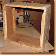
After everything was out, I cleaned the chassis with an ammonia-based cleaner. It was pretty grungy, so it took a while. This amp wasn't sitting in an attic for thirty-six years — this amp was played. For the faceplates I used mild dishwashing detergent instead, since I had no idea how ammonia reacts with paint and really didn't want to find out.
Then it was time to wire up the circuit board. It looked easy — there just isn't that much to it. The hard part was getting a good solder joint. Torres didn't have a board made specifically for the brown Princeton, so I bought one pre-drilled for a tweed Bassman; most of the holes were approximately right, so I only had to drill three or four more. The only way to get a good joint is to insert every component end into the hole at the same time and get them to stay put long enough for the solder to bond to the grommet. The phrase "pain in the ass" was uttered many times. It took about three hours.
The diagram
Once everything was mounted I started wiring the components together, and it took me five minutes to conclude that the original schematic just wasn't going to work. I had a poor-quality reproduction of the original black-and-white line drawing on letter paper — not the sort of thing that people with already poor eyesight need to stare at for hours. What I wanted was a multi-colour graphic representation of the physical layout that I could zoom in on.
I sat down at the computer and tried Photoshop, Illustrator, Visio and Corel, and in the end chose the most unlikely of programs: Microsoft PowerPoint 97. I'd only used it once or twice before, but a couple of its functions seemed tailor-made. I went through the original schematic, verified the circuit paths, and made a modern version. It took about four hours, and I was happy I took the time to do it right. For those who care, my diagram differs from the original in exactly one place: the original shows the brown and blue wires from the output transformer going to pin 3 on the two 6V6 tubes, which is the correct configuration, but the original diagram has them wired out of phase. Mine corrects it.


With the laptop out on the workbench, wiring went quickly — about three hours, and only that long because I double and triple checked every connection. Then I wired up a new three-prong power cord, reinstalled the chassis, and plugged it in. I'll admit I was nervous. I stood way back and used a really long screwdriver to flip the switch on the power strip. Yes, I felt like a doofus, but there was no possible way I was going to get shocked.
It didn't work
The light came on, and that was it. No sound, no hum, nothing. The tubes didn't even light up, which really worried me. My wife just laughed at me and went back inside the house, leaving me with my shame. Now that's love.
I opened it back up, numbered every solder point and went through them systematically. Within about ten minutes I'd found three mistakes, one so severe I had a hard time believing I'd actually done it — I'd wired what should have been power going to the power tubes straight to ground. That's why the tubes didn't light. So I fixed what I could find, went and got the wife to watch and to whack me with a 2x4 if I suddenly got really stiff, and turned it back on.
Nothing happened right away; the tubes had to warm up. But when they did I got a surprise. It made sound — the most awful screeching sound I have ever heard come from an amp, and I once saw Queensrÿche in concert, purely by accident I assure you, so I know what I'm talking about. This time the wife wasn't laughing, she just hightailed it into the house. But I was elated, because if it made that much noise the power section had to be working.
Torres, again
The next day I took the chassis up to Torres' shop and asked him to troubleshoot it. When I came back and asked what was wrong, Dan said "lots." Har har. Most of the problems were bad solder joints — they wouldn't stop the amp working, but they'd eventually pop off because the solder hadn't bonded to the grommets properly. Another problem was the resistors: I'd bent the wires too close to the core and changed their values. He explained that newer resistors are more forgiving, but that I should be careful not to bend so close next time. And I was right about the bias — it needed setting, so he took care of that, which bummed me out because I'd wanted to watch him do it.
But none of that was actually keeping the amp from working. What was stopping it, and causing the screeching, was that the output transformer wires were wired out of phase. I was very happy about this, because I knew I had done it correctly, which meant the schematic was wrong. I told Dan this and he said "bull," and I said "get out the schematic." So we did, and it turns out I was right.
Needless to say, I felt pretty good. I only use NOS RCA tubes in my vintage amps — it's the only thing I'm snobbishly adamant about — but Dan suggested a Sovtek 12AX7 for the preamp. I declined, stating my principles in no uncertain terms, until he said "trust me." It was only nine dollars, so I figured what the hell. It sounded pretty good, until you put it side by side with an NOS preamp tube. Sorry Dan, low marks on this one. It's a very high gain tube — so high it sounds like a mini-Marshall when you turn it up to eleven. I switched it out. I like my Fenders to sound like Fenders.
Skin
Electronically the amp was finished. Cosmetically it was a candidate for reconstructive surgery. The tolex was a horrible blonde, dirty and ripped, so that had to go. I ordered new brown tolex and when it arrived I noticed it was the pinkish brown — not my first choice, but it would have to do. Two cans of 3M spray adhesive from Home Depot and I got to work. The only really hard part was getting the old stuff off, which took a couple of hours. Measuring, cutting and applying the new tolex only took about ninety minutes. I also replaced the handle, the feet and the grill cloth.
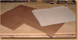

All in all it's a fine amp. Classic Fender sound, plenty of bottom end, the perfect gigging amp. Total time for the restoration was two weeks. And behold — the completed amp cometh.


